I’m trying to control a simulation using OpenPLC. I’ve designed and tested the model using OpenPLC running on the same PC as factoryIO, but now I want to move the PCL function to a network connected RaspberryPi. The Pi and OpenPLC are all working properly, but I’m unable to edit the Host address in the Modbus Server Configuration panel. It’s hard coded to the IP of the FactoryIO system.
Is this a bug?
1 Like
Hi @ronin48.
The host address is read-only on the ‘Modbus TCP/IP Server’ driver as the server will be running on the Factory IO system. The Modbus clients should then establish connection with the server using that address.
Will your RaspberryPi be acting as a Modbus client, or will it act as the server?
When the PI is the client you should use the ‘Modbus TCP/IP Server’ driver in Factory IO, and point the PI client to the host IP address displayed in Factory IO.
If using the PI as a Modbus server you should use the ‘Modbus TCP/IP Client’ driver in Factory IO. In that case you will be able to edit the ‘Host’ field.
1 Like
Hi @goncalo,
Thanks for the reply. I tried using the “Modbus Client” driver, with the Pi acting as the server, but the FactoryIO driver “channel mapping” appears to be messed up (not sure of the correct terminology, I’m new to PLC stuff). What I mean is, when I select the Client driver, I see “coils” on both sides of the PLC diagram, and no “Inputs”. I wondered if it was just a labelling mix-up, so tried running my program and both sides of the PLC are definitely acting as outputs - I see the “coil 4” object fire on both sides of the PLC at the same time.
For reference, here is the driver config:
As I say, I’m new to all this so freely admit I’ve probably made a mistake somewhere, and would appreciate some help fixing this.
Thanks.
1 Like
According to the Modbus protocol, the Modbus slave (server) provides the following object types to the Modbus master (client):
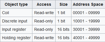
As you can see the client only has write-access to coils and holding register, so these have to be on the left side of Factory IO’s driver mapping.
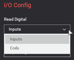
You can then choose whether to use coils or discrete inputs on the right side with the ‘Read Digital’ and ‘Read Register’ configuration options of the driver:
2 Likes
Ah, I see. Thanks for the clarification. I just assumed the left & right assignment was fixed.
Much obliged.
1 Like


